/

    Mission

    The mission of this satellite is the space demonstration of

    1. π/4 shift QPSK transmitter
    2. FSK transmitter
    3. Linear transponder
    4. Camera system
    These mission component will demonstrate operation for about one year from launch. And, they show that they are more practical than amateur radio communication devices and small camera for CubeSat.

    The mission of this satellite consists of seven as shown below.

    1.Demonstration of π/4 shift QPSK transmitter

    In this mission, the π/4 shift QPSK transmitter is operated in space, and the data output by the transmitter is downlinked and demodulated at the earth station. As data to output from the transmitter, fixed data set in communication device is used.


    2.Demonstration of FSK transmitter

    In this mission, the FSK transmitter is operated in space, and the data output by the transmitter is downlinked and demodulated at the earth station. As data to output from the transmitter, fixed data set in communication device is used.


    3.Show practically of π/4 shift QPSK transmitter

    This mission shows that the π/4 shift QPSK transmitter has a higher net communication speed(※1) and higher practically than the conventional communication device(※2). In order to evaluate practically, the orbit and weather conditions at the time of data downlink are recorded, and at the time of evaluation, we compare using the ones with the same environmental conditions.
    ※1:Net communication speed:Value obtained by dividing downlink data by communication time.
    ※2:Conventional communication device:A communication device that outputs data with AFSK modulation(1200bps) or GMSK modulation(9600bps) which has been widely used for CubeSat so far. In this satellite, it refers to a bus communication device.

    4.Show practically of FSK transmitter

    This mission shows that the FSK transmitter has a higher net communication speed(※1) and higher practically than the conventional communication device(※2). In order to evaluate practically, the orbit and weather conditions at the time of data downlink are recorded, and at the time of evaluation, we compare using the ones with the same environmental conditions.
    ※1:Net communication speed:Value obtained by dividing downlink data by communication time.
    ※2:Conventional communication device:A communication device that outputs data with AFSK modulation(1200bps) or GMSK modulation(9600bps) which has been widely used for CubeSat so far. In this satellite, it refers to a bus communication device.

    5.Demonstration of linear transponder

    In this mission, the linear transponder is operated in space, and the voice data is uplinked from the earth station in the 145 MHz band. Inside the satellite, uplinked voice is converted to 435 MHz band and outputted. Downlink the voice data output from the satellite at the earth station. For uplink voice, CW, SSB is used.


    6.Show practically of camera system

    In this mission, we take a picture of the earth using this system that can change resolution, image format and image effect widely. After shooting, send the earth image from the satellite and downlink the image data at the earth station.


    7.Fabrication of electric field intensity map of 145 MHz band at orbital altitude of 500km

    In this mission, we will investigate the field intensity of the 145MHz band around the satellite using the function of measuring it on the linear transponder. Based on the obtained data, we will create the filed intensity map indicating the state of field intensity across the world.


    ※Reference:Amateur Radio -PEOSAT “UWE-3”
    URL:http://www.pe0sat.vgnet.nl/satellite/cube-nano-picosats/uwe-3/


    Success criteria are defined as follows.

    Minimum success


    Mission1:Demonstration of π/4 shift QPSK transmitter

    Send the mission evaluation data from the satellite. If the data can be demodulated at the earth station, it will be achieved.


    Mission2:Demonstration of FSK transmitter

    Send the mission evaluation data from the satellite. If the data can be demodulated at the earth station, it will be achieved.

    Full success


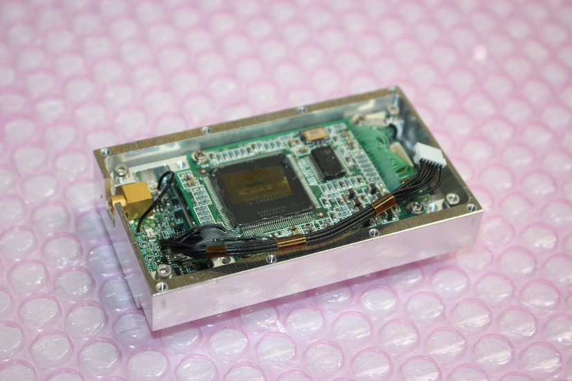
    Mission3:Show practically of π/4 shift QPSK transmitter

    Downlink various data using π/ shift QPSK transmitter. After the operation, the net communication speed is calculated from the communication time and the total amount of downlink data. During operation of the satellite, record the parameters shown below so that the environmental conditions are aligned. If we can show that the net communication speed is over 300% compared to conventional communication device, we achieve it.

    1. Temperature
    2. Humidity
    3. Atmospheric pressure
    4. Max elevation angle
    5. Orbit(North or South)


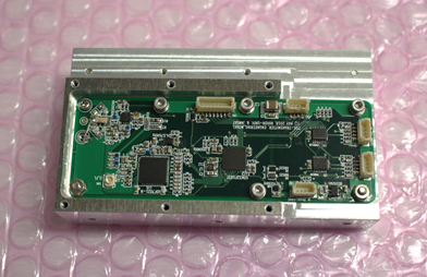
    Mission4:Show practically of FSK transmitter

    Downlink various data using FSK transmitter. After the operation, the net communication speed is calculated from the communication time and the total amount of downlink data. During operation of the satellite, record the parameters shown below so that the environmental conditions are aligned. If we can show that the net communication speed is over 150% compared to conventional communication device, we achieve it.


    1. Temperature
    2. Humidity
    3. Atmospheric pressure
    4. Max elevation angle
    5. Orbit(North or South)


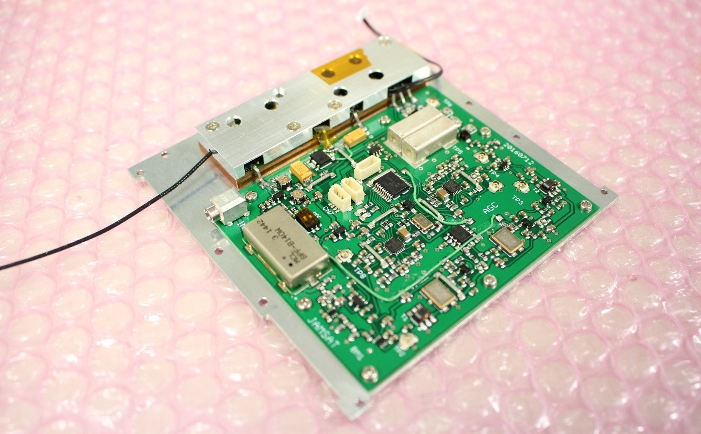
    Mission5:Demonstration of linear transponder

    Uplink audio data from the earth station toward the satellite in the 145MHz band. After the uplink is converted to the 435MHz band, it is outputted, so it is achieved when it can downlink at the earth station.


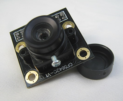
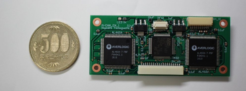
    Mission6:Show practically of camera system

    After setting the camera(※1), perform image shooting. Downlink the image and confirm that it is a normal image and achieve it.
    ※1:setting the camera:Resolution(over FHD),Image format(JPEG),Image effect(Initial value)

    Extra success


    Mission7:Fabrication of electric field intensity map of 145 MHz band at orbital altitude of 500km

    Using the linear transponder, measure the field intensity in the 145MHz band. It is achieved when the measured data can be downlinked and an field intensity map(※1) can be created.
    ※1 :field intensity map:The whole earth is divided into 36×18 blocks. Based on the obtained field intensity data, average field intensity on each block is calculated and color mapping is performed.